Cisco Packet Tracer (CPT) Lab Solutions - Build a Switch and a Router Network.
Easy steps to build your simple switch and router network
Overview
This Cisco Packet Tracer lab is a property of the Cisco Networking Academy, Skills for all with Cisco. This article seeks to bring solutions by displaying images and providing answers to the questions in the lab for better understanding.
Click the Cisco Packet tracer file to get the lab file to follow up with the solution.
Objectives
Configure PCs.
Configure a router.
Verify end-to-end connectivity.
Configure a switch.
Secure remote access to the router.
Background / Scenario
Your aunt owns a small insurance agency. She recently purchased a Cisco router and switch. She has two wired PCs that need to be connect to the network. She is proud of your progress in your networking course and asked you if you would like to demonstrate your skills. Your job is to connect the devices, implement a basic configuration, and verify connectivity. After network connectivity has been verified, you will use IOS commands to retrieve information from the devices to answer questions about your network equipment. You will also configure the router for secure remote access.
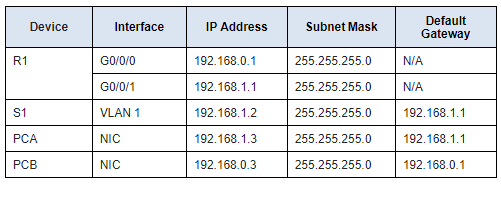
Addressing Table
Instructions
Part 1: Configure PCs.
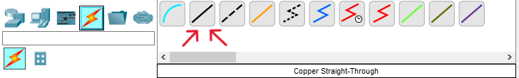
Step 1: Connect the devices.
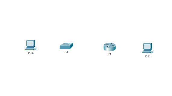
a. First, you will connect the devices using Copper Straight-Through cables.
b. Connect R1 G0/0/1 to any port on S1. Connect to the FastEthernet port of the switch
c. Connect to the FastEthernet port of PCA to any port on S1.
d. Connect to the FastEthernet port of PCB to R1 G0/0/0.
Step 2: Assign addresses to the PCs
In this step, you will assign static IPv4 addressing information to the PC interfaces. Use the information in the Addressing Table to complete the task.
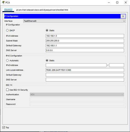
a. Configure the IPv4 address, subnet mask, and default gateway settings on PCA . Click on PCA, and click on IP Configuration in the Desktop tab. The following values are found in the Addressing Table. Enter them in the IP Configuration for PCA.
- IP Address: 192.168.1.3
- Subnet Mask: 255.255.255.0
- Default Gateway: 192.168.1.1
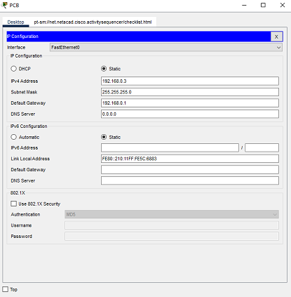
b. Configure the IPv4 address, subnet mask, and default gateway settings on PCB . Click on PCB, same way you clicked on PCA, to open the IP Configuration of PCB.
The following values are found in the Addressing Table. Enter them in the IP Configuration for PCB .
- IP Address: 192.168.0.3
- Subnet Mask: 255.255.255.0
- Default Gateway: 192.168.0.1
Test connectivity between PCA and PCB.
Ping between PCA and PCB.
In the PCA Command Prompt, enter the ping 192.168.0.3 command. You can also open the PCB Command Prompt, and then enter the ping 192.168.1.3 command.
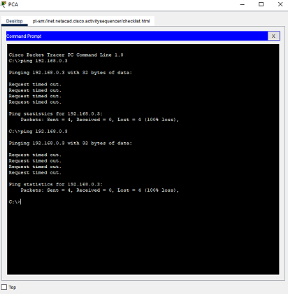
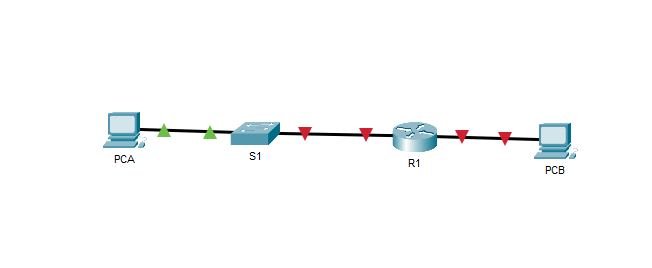
You will notice that the pings failed.
Question 1:
Why were the pings not successful?
Click here for answer
The router interfaces, which are the default gateways for each PC, have not been configured yet; therefore, the ping traffic is not being routed between the PCA and PCB networks. Note that link lights on the connections from the router are red. This indicates that the links are not functioning.Part 2: Configure a router.
In this step, you will use the CLI tab for R1 to configure basic settings. You can connect a Console cable and access the CLI from PCA or PCB, if you wish. However, in this activity, you can also just click R1 to open it.
a. Assign a hostname according to the Addressing Table.
Click R1, in the CLI tab enter the following command:
1
2
3
Router> enable
Router# configure terminal
Router(config)# hostname R1
b. Assign class as the privileged EXEC encrypted password.
Configure the privileged EXEC mode password in global configuration mode with the following command:
1
R1(config)# enable secret class
c. Assign cisco as the console password and enable login.
Enter line configuration mode in global configuration mode and configure the console password with the following command:
1
2
3
R1(config)# line con 0
R1(config-line)# password cisco
R1(config-line)# login
d. Encrypt the plaintext passwords.
Encrypt plaintext passwords with the following command in global configuration mode:
1
R1(config)# service password-encryption
e. Create a banner that warns anyone accessing the device that unauthorized access is prohibited.
Configure a banner with the following command:
1
R1(config)# banner motd $Authorized Access Only!$
In this example, $ is the delimiter.
f. For G0/0/0, configure IP addressing according to the Addressing Table and activate the interface.
Enter interface configuration mode and configure the G0/0/0 interface with the following command:
1
2
3
R1(config)# interface g0/0/0
R1(config-if)# ip address 192.168.0.1 255.255.255.0
R1(config-if)# no shutdown
g. For G0/0/1, configure IP addressing according to the AddressingTable and activate the interface.
First, enter exit to move out from the interface G0/0/0
1
R1(config-if)# exit
Enter interface configuration mode with the following command:
1
2
3
R1(config)# interface g0/0/1
R1(config-if)# ip address 192.168.1.1 255.255.255.0
R1(config-if)# no shutdown
h. Save the running configuration to the startup configuration file.
Save the configuration with the following command:
1
2
3
4
5
6
R1(config)# exit
R1# copy running-config startup-config

Destination filename [startup-config]?
Building configuration...
[OK]
Click Enter to save in the startup-config filename
You can also use the abbreviated copy run start or the write mem command.
Close the R1 CLI tab.
Part 3: Verify end-to-end connectivity.
Now, let’s test connectivity between PCA and PCB again.
Ping between PCA and PCB.
In the PCA Command Prompt, enter the ping 192.168.0.3 command. You can also open the PCB Command Prompt, and then enter the ping 192.168.1.3 command.
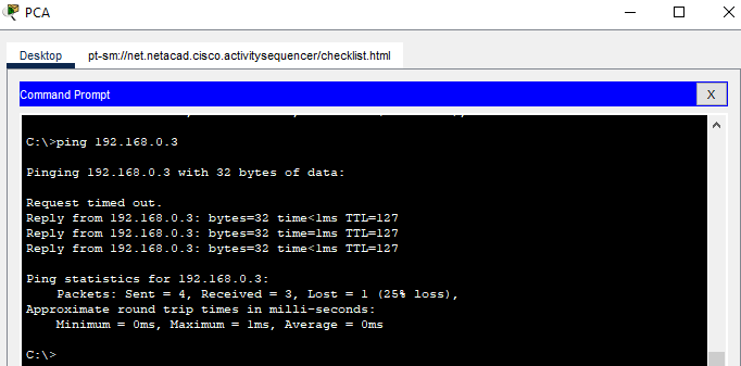
It worked this time.
Question 2:
Why were the pings between PCA and PCB successful?
Click here for answer
The router is routing the ping traffic across the two networks. The default settings for the 2960 switch will automatically enable the interfaces that are connected to devices.Part 4: Configure a switch.
In this step, you will use the CLI tab for S1 to configure basic settings. You can connect a console cable and access the CLI from PCA or PCB, if you wish. However, in this activity, you can also just click S1 to open it.
a. Assign a hostname according to the Addressing Table.
Click S1. Then enter the following command:
1
2
3
Switch> enable
Switch# configure terminal
Switch(config)# hostname S1
b. Assign class as the privileged EXEC encrypted password.
Configure the privileged EXEC mode password in global configuration mode with the following command:
1
S1(config)# enable secret class
c. Assign cisco as the console password and enable login.
Enter line configuration mode in global configuration mode with the following commands:
1
2
3
S1(config)# line con 0
S1(config-line)# password cisco
S1(config-line)# login
d. Encrypt the plaintext passwords.
Encrypt plaintext passwords with the following command in global configuration mode:
1
S1(config)# service password-encryption
e. Create a banner that warns anyone accessing the device that unauthorized access is prohibited.
Configure a banner with the following command:
1
R1(config)# banner motd $Authorized Access Only!$
In this example, $ is the delimiter.
f. For VLAN 1, configure IP addressing according to the Addressing Table and activate the interface.
Enter interface configuration mode with the following commands:
1
2
3
S1(config)# interface vlan 1
S1(config-if)# ip address 192.168.1.2 255.255.255.0
S1(config-if)# no shutdown
g. Configure the default gateway according to the Addressing Table.
Configure the default gateway with the following command:
1
S1(config)# ip default-gateway 192.168.1.1
h. Save the running configuration to the startup configuration file.
Save the configuration with the following command:
1
2
3
4
5
S1(config)# exit
S1# copy running-config startup-config
Destination filename [startup-config]?
Building configuration...
[OK]
Click Enter to save to the startup-config filename.
You can also use the abbreviated copy run start or the write mem command
Part 5: Secure remote access to the router.
Step 1: Secure remote access to R1.
a. On R1, configure the domain name as academy.net.
Log back in to R1 with the password cisco, enter privileged EXEC mode with the password class. Enter the following command:
1
R1(config)# ip domain-name academy.net
b. Generate RSA keys with a 1024 key length.
Enter the following command to generate keys:
1
2
3
4
5
6
7
8
9
R1(config)# crypto key generate rsa

The name for the keys will be: R1.academy.net
Choose the size of the key modulus in the range of 360 to 4096 for your
  General Purpose Keys. Choosing a key modulus greater than 512 may take
  a few minutes.

How many bits in the modulus [512]: 1024
Enter 1024 as the key length.
c. Create a user with SSHuser as the username and cisco as the secret password.
Enter the following command:
1
R1(config)# username SSHuser secret cisco
d. Configure the VTY lines to use the local username database for login credentials.
The VTY lines should only allow SSH for remote access.
Enter the following command:
1
2
3
R1(config)# line vty 0 4
R1(config-line)# login local
R1(config-line)# transport input ssh
Step 2: Verify SSH remote access.
Now, let’s verify SSH remote access. From PCA or PCB, use the Command Prompt to establish a secure session with R1. At the prompt, use the ssh command.
Click either PCA or PCB, open the Command Prompt, and then enter the following command:
1
C:\> ssh -l SSHuser 192.168.1.1
The password is cisco.
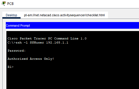
You have successfully verified that SSH is correctly configured on R1
Question 3:
If the G0/0/1 interface status is administratively down, what interface configuration command would you use to activate the interface?
Click here for answer
R1(config-if)# no shutdownQuestion:
Question 4:
What would happen if you had incorrectly configured interface G0/0/1 on the router with an IP address of 192.168.1.2?