Cisco Packet Tracer (CPT) Lab Solutions - Implement Basic Connectivity.
Performing basic connectivity of end devices and switches.
Overview
This Cisco Packet Tracer lab is a property of the Cisco Networking Academy, Skills for all with Cisco. This article seeks to bring solutions by displaying images and providing answers to the questions in the lab for better understanding.
Click the Cisco Packet tracer file to get the lab file to follow up with the solution.
Addressing Table
| Device | Interface | IP Address | Subnet Mask |
|---|---|---|---|
| S1 | VLAN 1 | 192.168.1.253 | 255.255.255.0 |
| S2 | VLAN 1 | 192.168.1.254 | 255.255.255.0 |
| PC1 | NIC | 192.168.1.1 | 255.255.255.0 |
| PC2 | NIC | 192.168.1.2 | 255.255.255.0 |
Objectives
Part 1: Perform a Basic Configuration on S1 and S2
Part 2: Configure the PCs
Part 3: Configure the Switch Management Interface
Background / Scenario
In this activity, you will first perform basic switch configurations. Then you will implement basic connectivity by configuring IP addressing on the switches and PCs. When the IP addressing configuration is complete, you will use various show commands to verify configurations and use the ping command to verify basic connectivity between devices.
Instructions
Part 1: Perform SVI Configuration on S1 and S2
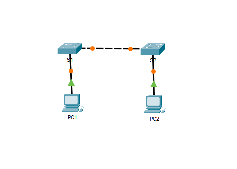
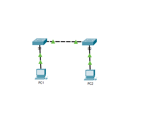
Click the Fastforward icon to turn the connections to green,
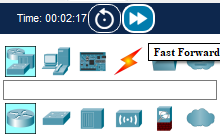
Or, you wait for few seconds to allow the connections automatically turn green.
Step 1: Configure S1 with a hostname.
Open configuration window
a. Click S1, and then click the CLI tab.
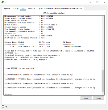
b. Enter the privileged EXEC mode. Then enter the global configuration mode.
1
2
3
4
5
Switch> enable

Switch# configure terminal

Enter configuration commands, one per line. End with CNTL/Z.
c. Configure the hostname as S1.
1
2
3
Switch(config)# hostname S1

S1(config)#
Step 2: Configure S1 with an IP address.
Switches can be used without any configurations. Switches forward information from one port to another based on Media Access Control (MAC) addresses.
Question 1: Why does a switch need an IP address?
Click here for answer
An IP address is required to connect to a switch remotely. The switch is managed through VLAN1 by default.a. In the global configuration mode, enter the following commands to configure S1 with an IP address in VLAN 1.
1
2
3
4
5
6
7
S1(config)# interface vlan 1

S1(config-if)# ip address 192.168.1.253 255.255.255.0

S1(config-if)# no shutdown

%LINEPROTO-5-UPDOWN: Line protocol on Interface Vlan1, changed state to up
Question 2: What does the no shutdown command do?
Click here for answer
The no shutdown command administratively enables the interface to an active state.b. Exit the configuration mode and save the configuration.
1
2
3
4
5
6
7
8
9
10
11
S1(config-if)# end

S1#

S1# copy running-config startup-config

Destination filename [startup-config]?

Building configuration...

[OK]
c. Verify the IP address configuration on S1.
1
2
3
4
5
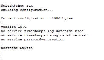
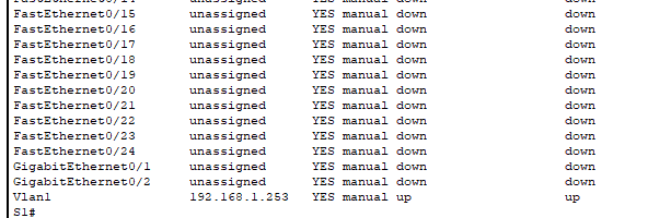
S1# show ip interface brief
<output omitted>
Vlan1 192.168.1.253 YES manual up up
close the configuration window
Step 3: Configure S2 with a hostname and IP address.
In this step, you will configure S2 with a hostname and IP address.
open configuration window
a. Click S2. In the CLI tab, enter the global configuration mode.
b. Configure the switch S2 with a hostname using the information according to the Addressing Table.
c. Use the information in the Addressing Table, repeat the same process to configure the switch S2 with an IP address.
d. Exit the configuration mode. Verify the IP address configuration on S2.
1
2
3
4
5
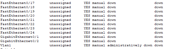
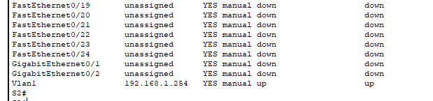
S2# show ip interface brief
<output omitted>
Vlan1 192.168.1.254 YES manual up up
e. Save the configuration file to NVRAM. Enter the copy running-config startup-config command to save the configuration.
close configuration window
Part 2: Configure the PCs
In this part, you will configure PC1 and PC2 with IP addresses and verify network connectivity.
Step 1: Configure both PCs with IP addresses.
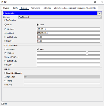
a. Click PC1, and then click the Desktop tab.
b. Click IP Configuration. In the Addressing Table above, you can see that the IP address for PC1 is supposed to be 192.168.1.1 and the subnet mask 255.255.255.0. Enter this information for PC1 in the IP Configuration window.
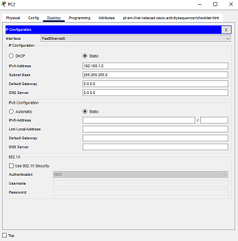
c. Repeat the previous steps for PC2. Use the IP address listed in the Address Table for PC2.
Step 2: Test connectivity from the PCs.
a. Click PC1. Close the IP Configuration window if it is still open. In the Desktop tab, click Command Prompt.
b. Enter the ping command and the IP address for S1.
1
2
3
Packet Tracer PC Command Line 1.0

PC> ping 192.168.1.253
Question 3: Were you successful? Explain.
Click here for answer
It should not be successful because the switches have not been configured with an IP address.f. From PC1, ping S2 and PC2.
g. Repeat the pings to S1, S2, and PC1 from PC2.
All pings should be successful. If your first ping result is 80%, retry; it should now be 100%. You will learn why a ping may fail the first time later in your studies. If you are unable to ping any of the devices, check your configuration for errors.
Step 3: Verify network connectivity from the switches.
Network connectivity can be verified using the ping command. It is very important that connectivity exists throughout the network.
a. From S1, ping the other devices in the network. The ping to PC1 is displayed below as an example.
1
2
3
4
5
6
7
8
9
S1> ping 192.168.1.1

Type escape sequence to abort.

Sending 5, 100-byte ICMP Echos to 192.168.1.1, timeout is 2 seconds:

!!!!!

Success rate is 100 percent (5/5), round-trip min/avg/max = 0/0/1 ms
b. From S2, ping the other devices in the network.
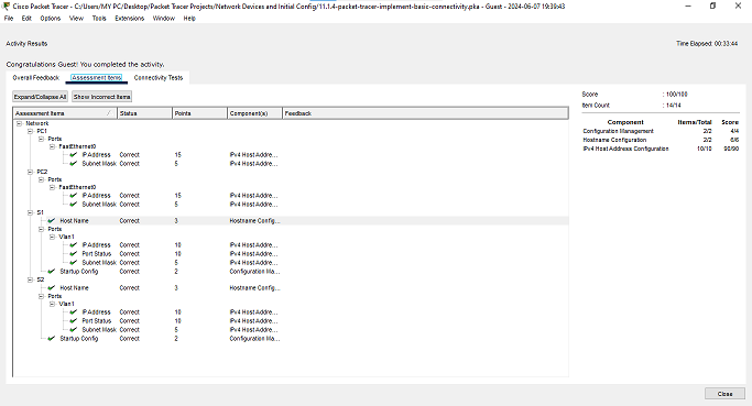
All pings should be successful. If your first ping result is 80%, retry; it should now be 100%. If you are unable to ping any of the devices, check your configuration for errors. Click the Check Results button to see if you completed the tasks of the lab.